Novel Waveguide Connectors to Simplify Microwave and Millimeter-wave Component Packaging
Published: June 2022, IEEE International Microwave Symposium
Yonghui Shu, Lingyun Ren
Eravant, USA
Abstract—In this paper, a novel field replaceable waveguide connector, which is similar to a field replaceable coaxial connector, is described. For three popular frequency bands, Ka, Q and U, waveguide connectors are simulated, designed, and fabricated for component integration. The concept is applicable to a wide range of waveguide frequency bands where glass beads are available for standard RF feedthroughs, reaching as high as 110 GHz in WR-10. Prototypes and initial production data have shown full waveguide band coverage, with RF performance comparable to that of coaxial connectors. The waveguide connectors can be used as drop-in replacements for coaxial connectors found in many existing RF component packages where the waveguide interface is desired.
Keywords— waveguide, RF connector, waveguide connector, coaxial connector, full band, insertion loss, return loss.
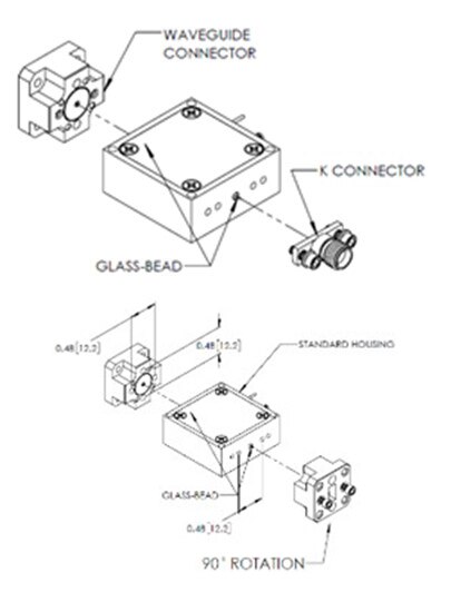
Fig. 1. Field replaceable coaxial and waveguide connectors.
Many publications describe broadband transitions from waveguide to microstrip line [3], [4] and to other transmission line formats such as finline [5], [6] and coplanar waveguide [7]. From these publications, circuit-to-waveguide interfaces are often considered as one unified element. Therefore, many waveguide interfaced packages are custom designs that require non-recurring engineering (NRE) efforts including EM simulations, mechanical designs, and prototyping. These efforts cause increased product development costs, longer design cycles and greater inventory management burdens. In addition, custom designed housings have no flexibility in terms of port designations, such as waveguide input and coaxial output connectors, or in terms of port orientations such as vertical or horizontal waveguide ports. Furthermore, to hermetically seal such a waveguide port is always challenging and expensive. It would be desirable therefore if a waveguide connector, much like the field replaceable coaxial connector, could work with standard glass-bead pins. Such a connector would utilize standard housings designed for field replaceable coaxial connectors and eliminate the effort of designing custom transitions from waveguide to other transmission media. Based on this, the concept of the field replaceable waveguide connector is proposed as shown in Fig. 1.
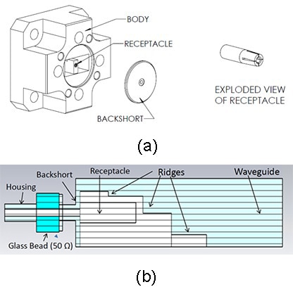
Fig. 2. (a) The configuration of the waveguide connector; (b) The CST model of the waveguide connector.
To demonstrate the concept, Ka, Q and U band field replaceable waveguide connectors were simulated, designed, and fabricated to cover the frequency range of 26.5 to 60 GHz. Measured insertion loss and return loss are consistent with EM simulations. Many units fabricated in a production environment demonstrate repeatable performance. The typical insertion loss for Ka, Q and U Band waveguide connectors is 0.5 to 0.7 dB with return loss around 20 dB. These results are comparable to their counterparts, the 2.92 mm, 2.4 mm and 1.85 mm coaxial connectors. Therefore, waveguide connectors with electrical performance similar to that of coaxial connectors are realized. Additionally, the waveguide connectors are mechanically interchangeable with their coaxial alternatives. These results have the potential to revolutionarily change and improve waveguide interfaced component packaging technologies.

Fig. 3. Simulated insertion loss and return loss of (a) WR-28, (b) WR-22, and (c) WR-19.
As shown in the Fig. 2 (b), a three-step single ridged waveguide transformer is adapted for the connector body design. The CST EM simulator is used to optimize the in-band return loss and insertion loss to achieve the best performance within the mechanical and manufacturing boundaries. The performance of the connector versus various mechanical tolerances is simulated to determine the critical dimensions so that the best performance and highest production yield can be achieved. It is found that height of the last stage of the ridge, the back-short position, and the concentricity of the coaxial line are the most critical dimensions. The optimal performance of simulated waveguide to coaxial transitions is shown in Fig. 3. The key considerations of the mechanical design include the receptacle dimensions, the receptacle material, and its implementation. Once the receptacle dimensions are chosen, the ridged waveguide thickness can be determined. The number of mounting holes, as well as their size and locations, are considered carefully to achieve interchangeability with industry-standard field replaceable coaxial connectors.
The connector receptacle is a key component to ensure a reliable RF and mechanical connection between the impedance transformer and the glass-bead pin. By studying the receptacles for industry-standard 2.92 mm, 2.4 mm, and 1.85 mm coaxial connectors, the receptacle hole is decided for receiving 0.012 mil diameter pins. The durable and spring-action-friendly material, beryllium copper, is selected for the receptacle. To ensure a successful manufacturing process and high yield, the mechanical design is based on press-fit assembly technology. It is implemented to ensure accurate, reliable, and consistent production. Mounting holes are sized for 2-56 screws with 0.480-inch separation. Considering the flexibility of the waveguide orientation, the 90-degree rotation option is supported by the inclusion of two additional mounting holes.
Final implementations for two waveguide connectors are shown in Fig. 4 (a). The text notations in Fig. 4 (b) indicate the port configurations. WG(V)–WG(V) represents waveguide ports with vertical orientation for both the input and output. Similarly, K(F) – WG(H) indicates a female K connector as the input port with waveguide having horizontal orientation as the output port, etc.
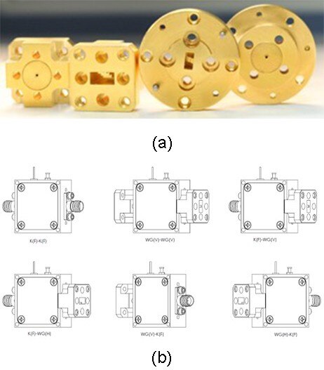
Fig. 4. (a) Mechanical illustration of the waveguide connectors; (b) Device illustration by using the waveguide connectors.
Many devices with standard RF feedthroughs (glass beads) for coaxial connectors, such as attenuators, switches, mixers, TX/RX modules, etc. can be configured with the waveguide interfaces without any additional efforts. The benefits of using the waveguide connectors include:
• Provides flexibility to configure the package with various RF interfaces using housings with standard coaxial (glass-bead) feedthroughs.
• Maintains a sealed package while avoiding expensive hermetically sealed waveguide windows.
• Avoids custom packaging NRE and reduces the cycle time by using standard coaxial feedthrough (glass-bead) housings.
• Improves inventory efficiency by stocking only a few standard coaxial feedthrough (glass-bead) housings.
• Eliminates various adapters or waveguide interconnecting components and their insertion losses when integrating various devices into sub-assemblies for radar, communication, instrumentation, etc.
Waveguide connectors for other common waveguide bands, are also developed.

Fig. 5. Measured insertion loss and return loss of (a) WR-28, (b) WR-22 and (c) WR-19.
[2] “Hermetic Solutions,” Catalog 2018, Thunderline-Z.
[3] Y. Leong and S. Weinreb, “Full Band Waveguide-to-Microstrip Probe Transitions,” IEEE MTT-S Int. Microw. Symp. Dig., June 1999.
[4] A. Mozharovskiy et al., “Wideband Probe-Type Waveguide-to-Microstrip Transition for 28 GHz Applications,” 48th Eur. Microw. Conf. (EuMC), pp.113-116, Sept. 2018.
[5] S. Jing et al., “Waveguide-to-Microstrip Antipodal Finline Transition at W Band,” Proc. Int. Conf. Instrum. Meas. Comput. Commun. Control. (IMCCC), pp. 510-513, 2013.
[6] V. S. Mottonen, "Wideband Coplanar Waveguide-To-Rectangular Waveguide Transition Using Fin-Line Taper," IEEE Microw. Wirel. Compon. Lett., vol. 15, no. 2, pp. 119-121, Feb. 2005.
[7] R. Fang et al., "Coplanar waveguide-to-rectangular waveguide transition using meander slotline," Asia Pac. Microw. Conf. (APMC), pp. 399-402, 2011.
[8] K. V. Hoel and S. Kristoffersen, "3D Printed Broadband Double-Ridged Waveguide to Coax Transition," 14th Eur. Conf. Antennas Propag. (EuCAP), 2020.
[9] K. K. Chan, R. Martin and K. Chadwick, "A broadband end launched coaxial-to-waveguide transition for waveguide phased arrays," IEEE Antennas Propag. Soc. Int. Symp. USNC/URSI Natl. Radio Sci. Meet. APSURSI 1998 - Proc., June 1998.
[10] (2019) The Eravant website. [Online]. Available: https://www.eravant.com/6-db-correction-on-waveguide-to-coax-adapter-return-loss