High-Power Handling, Amplitude and Phase stable, Full Band WR-06 Rotary Joint
Published: June 2025, IEEE International Microwave Symposium
Abstract — This paper presents the industry’s first WR-06 full waveguide band rotary joint. The joint is a novel design, which is capable of high-power handling and delivers superior amplitude and phase stabilities. With a typical phase variation of ±1.0 degrees and amplitude variation of ±0.1 dB over a full 360° rotation, the WR-06 rotary joint can easily be configured into various input and output arrangements, such as L-style, I-Style and U-Style models.
Keywords — Millimeter-wave, Sub-THz, Full Waveguide Bandwidth, Rotary Joint, TE01 Mode, High Power Handling, WR-06.
I. INTRODUCTION
Typically deployed in beam scanning, a rotary joint is a type of microwave device that allows for transmission of radiofrequency (RF) signals as it rotates. The rotary joint comprises of two components—the rotor, which is typically attached to an antenna, and the stator, which would be attached to a transceiver. With a rotary joint, beam scanning or polarization rotation are achieved by variation the angles of the antenna-mounted rotor, driven by a manual mechanism or a motor.
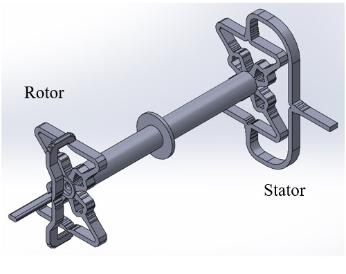
Fig. 1. Waveguide Structure
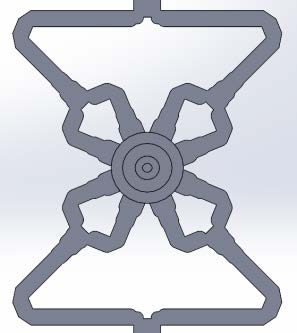
Fig. 2. 1:8 Power Divider Structure
As rotation is a primary part of its application, a rotary joint typically utilizes a coaxial or circular waveguide structure for transmission of RF signals between the input and output ports. A coaxial type rotary joint utilizes TEM mode [1-2] while the circular waveguide type utilizes TE01 and TM01 modes [3-5]. Both rotary joint types feature a mechanical discontinuity between the rotor and stator, which is where an inner conductor is located for a coaxial type rotary joint, and is where a choke slot is placed for a circular waveguide rotary joint. While full band operation is achievable with TEM mode rotary joints, the manufacturability of the coaxial structure becomes less feasible at higher frequencies due to the smaller wavelength, as the inner conductor diameter needed for the coaxial structure becomes extremely small. Not only does that make the structure difficult to produce, but also to assemble, which results in inconsistent performance and service life. In addition to this, a small inner conductor limits the power handling capabilities of a rotary joint.
The D-Band, 110 to 170 GHz, commonly known as WR-06 waveguide is drawing increased attention in recent radar, wireless communication, public safety, etc. system applications. A WR-06, L-style, waveguide rotary joint is described in the paper, building off the work that was previously done on a WR-15 rotary joint [6]. The WR-06 rotary joint was designed, manufactured, and tested, displaying exceptional phase and amplitude stability and high-power handling capability due to the structure being a contactless and full waveguide. This design was also easily adapted to I-Style and U-Style configurations.
II. CONCEPT DESIGN AND SIMULATION RESULTS
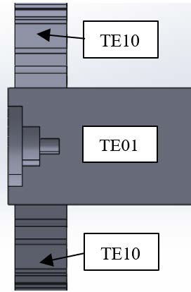
Fig. 3. Impedance matching structure for circular waveguide
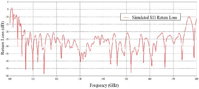
Fig. 4. Simulated Return Loss
The WR-06 rotary joint design builds on previous work on the WR-15 high power rotary joint [6], which utilizes a full waveguide structure for propagation of TE10 and TE01 modes. Circular waveguide is chosen as the transmission method between the rotor and stator to allow for high power handling capability. The waveguide structure as shown in Fig. 1 is split into two and rotation is achieved by use of ball-bearings. A choke slot structure is designed into the mechanical discontinuity caused by this so that it does not affect electrical performance.
One of the difficulties encountered in the WR-06 rotary joint design is the smaller waveguide structures. Larger step structures in the waveguide found in WR-15 were not difficult to manufacture by CNC, however the smaller step structures inherent to WR-06 size required that a slightly different assembly structure be used that incorporates small shims to maintain sharp corners on the waveguide where needed.
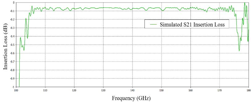
Fig. 5. Simulated Insertion Loss
A 1 to 8 power divider structure shown in Fig. 2 is used to convert the input TE10 mode signal into TE01 mode found in the rotational structure, and then back to TE10 mode for the output. Step structures in Fig. 3 were designed at the rectangular-to-circular waveguide transitions to improve impedance matching. Additional impedance matching steps were designed within the TE10 power divider structure.
The minimum circular waveguide size was determined using the below equation as was done in previous work [6].
r > 1.66 mm (2)
Using λc = 2.73 mm, which is the WR-06 cutoff wavelength at 110 GHz, and P01 = 3.832 - the first root of the Bessel function, minimum circular waveguide radius r was calculated. In the end, radius r of 1.85mm was used to allow room for impedance matching structures to be placed at the ends of the circular waveguides.
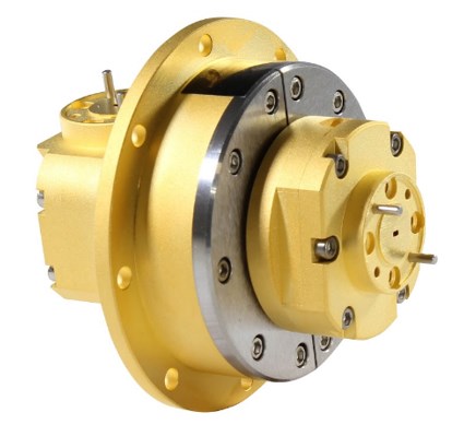
Fig. 6. WR-06 L-Style Rotary Joint
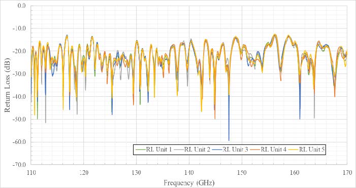
Fig. 7. Measured Return Loss
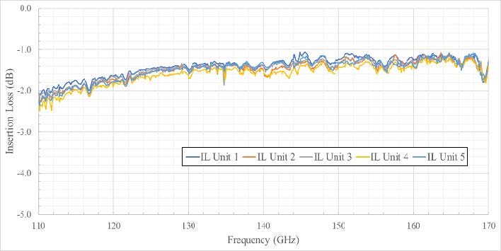
Fig. 8. Measured Insertion Loss
The simulated return loss is shown on Fig. 4 and simulated insertion loss is shown on Fig. 5, respectively. While the simulated return loss is better than -20 dB typically, the insertion loss is better than 0.10 dB.
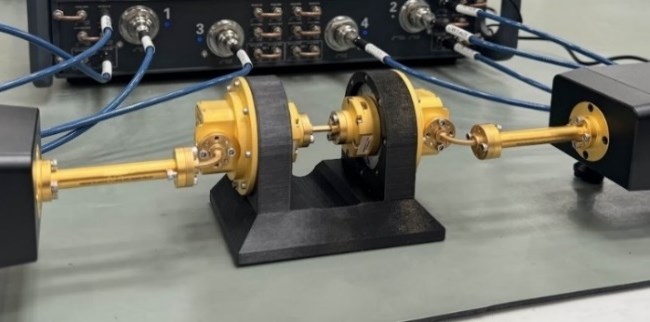
Fig 9. Test setup for phase and amplitude stability measurements
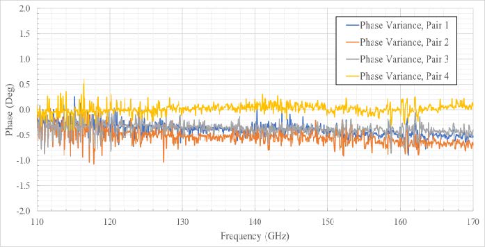
Fig. 10. Measured Phase Variation
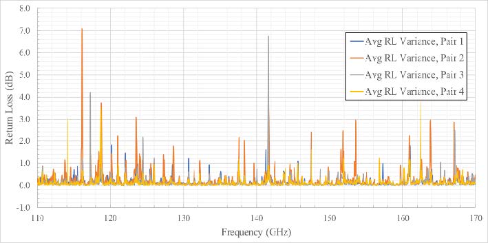
Fig. 11. Measured Return Loss Variation
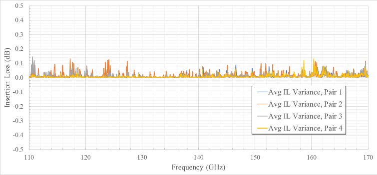
Fig. 12. Measured Insertion Loss Variation
III. FINAL DESIGN MEASURED RESULTS
The three types of rotary joints, L-Style, I-Style and U-Style designs were manufactured, assembled, and tested on a WR-06 Vector Network Analyzer. While all three style rotary joints exhibit similar RF performance, this paper is to present the L-Style rotary joints’ results only. The photo of the hardware is shown in Fig. 6. A total of five units were manufactured by the company’s production line. In the interest of convenience for testing, a pair of rotary joints were used. Both waveguide ports on each unit were connected to the VNA extenders for taking return loss and insertion loss measurements shown in Fig. 7 and Fig. 8 respectively. Measurements between 110-170 GHz were taken-- the measured return loss is 15 dB typical while the measured insertion loss is 1.8 dB typical. These discrepancies between the measured and simulated data are seen are mainly due to the mechanical realization needed to achieve the waveguide structure shown in Fig. 1. In order to achieve the structure, the individual parts composing the rotary joint needed to be designed such that it is machinable on a CNC machine. During assembly, it is possible that small mechanical mismatches are present along the waveguide structure due to machining tolerances and surface finishing that might have caused additional mismatch and circuit loss, thus degrading the final performance. This may be improved with the adoption of more careful mechanical tolerance control or surface finishing quality control or more involved assembly procedures. The machining quality of the waveguide and the flatness of mating surfaces must also be taken into account when evaluating the performance of this type of rotary joint.
Phase and amplitude measurements throughout the rotary joint rotation were also taken. Two rotary joints were fixed to a 3D printed fixture on a mounting flange designed on the stator and the in-line ports were connected by a waveguide straight. H-plane waveguide bends were used to connect the right-angle ports of the rotary joints to VNA extenders. With this setup, the stators of both rotary joints, fixed to the extenders, remain stationary while the rotors are free to rotate. The test setup can be seen in Fig. 9. Data was recorded for two rotary joints simultaneously, at 4 positions—the starting position being designated as 0°, and another 3 positions measured 90° apart from each other. The difference of phase and amplitude between each position was calculated and averaged for each pair, then shown in Fig. 10, Fig. 11 and Fig. 12, respectively. It can be seen that throughout the rotation of the rotary joint, the phase variation is within ±1.0°, average return loss variation is less than 0.20 dB, and the insertion loss variation is largely within 0.1 dB. With this, the consistent performance of all five units can be observed.
IV. CONCLUSION
The viability of a full band, WR-06 rotary joint based on TE01 transmission mode was demonstrated. These rotary joints shown excellent phase stability of ±1.0 degrees and amplitude stability of ±0.1 dB over the entire WR-06 waveguide bandwidth and over its 360 degrees of rotation. Compared to TEM rotary joints, which utilize an inner conductor, this full waveguide design features higher power handling capacity and is easily manufacturable as well as configurable as I-Style and U-Style type rotary joints. Future work may be to adapt this type of design for frequencies up to 330 GHz.
ACKNOWLEDGMENT
The authors would like to thank the Eravant team for their assistance in developing this rotary joint.
REFERENCES
[1] M. T. Azim, J. Park and S. -O. Park, "Contactless Linear Rotary Joint at Ku-Band," in IEEE Microwave and Wireless Components Letters, vol. 29, no. 6, pp. 373-375, June 2019, doi: 10.1109/LMWC.2019.2912271.
[2] Torpi, Hamid, Bostan and Salih Mehmed, “ Ku Band Rotary Joint Design for SNG Vehicles,”
[3] Deng Bin, Zhang Hua-lin and M. -c. Hu, "An analysis of circular waveguide Rotary Joint design with coupling TM01 mode," Proceedings of 2011 IEEE CIE International Conference on Radar, Chengdu, 2011, pp. 1224-1227, doi: 10.1109/CIE-Radar.2011.6159776.
[4] M. T. Azim, J. Park, L. Minz, R. S. Aziz and S. -o. Park, "Single Channel Linear Rotary Joint at X-band," 2018 International Symposium on Antennas and Propagation (ISAP), Busan, Korea (South), 2018, pp. 1-2.
[5] V. I. Abramov, Hun-Joong Park, Dong-Hyun Kim and Tae-Hyung Lee, "U-style rotary joint with E/sub 01/ mode for millimeter waves," 2004 IEEE MTT-S International Microwave Symposium Digest (IEEE Cat. No.04CH37535), Fort Worth, TX, USA, 2004, pp. 1879-1882 Vol.3, doi: 10.1109/MWSYM.2004.1338974.
[6] A. H. Chen, A. Chen and Y. Shu, "A WR-15 High-Power Handling, Amplitude and Phase Stable Full Band Rotary Joint Based on TE01 Mode," 2024 54th European Microwave Conference (EuMC), Paris, France, 2024, pp. 525-528, doi: 10.23919/EuMC61614.2024.10732502.