Full-Band Millimeter Wave Waveguide Magic Tees and Power Dividers for Manufacturing Ability
Published: January 2022, 52nd European Microwave Conference
Abstract— In this paper, a full-band millimeter wave waveguide magic tee design that is friendly to computer numerical controlled (CNC) machining, manufacturing assembly and industrial standard production processes is presented. Traditional magic tee designs either barely cover the full waveguide bandwidth or are difficult to fabricate with consistent electrical performance. An improved magic tee junction utilizes a simple post in the middle of the junction and stepped waveguide transformers to provide the mechanical mate with standard waveguide openings and flanges. The dimensions of the magic tee junction are EM simulated and optimized by considering the variations of the manufacturing process for optimal performance and high reproducibility. An E-band magic tee and a V-band four-way power divider are presented to demonstrate the improved designs. The newly developed magic tee and power divider have shown good performance for full band coverage with high production yields in manufacturing environments.
Keywords— Waveguide, magic tee, power divider, full band, insertion loss, return loss, isolation, CNC machining, production
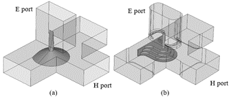
Fig. 1. Traditional magic tee designs with (a) cone and sharp pin (b) stepped post and pin in the middle of junction.
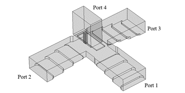
Fig. 2. Proposed magic tee design.
The examples presented in Fig. 1. and Fig 2. are typical of numerous magic tee designs and applications, but they lack the full waveguide band coverage that is desirable in broadband applications. In [1], a magic tee composed of a septum and metallic platform is proposed for a broad bandwidth of 16% in the Ka-band. In [2], an X-band magic tee with a stepped conducting cone is optimized using a genetic swarm optimization to accomplish 20 dB return loss with bandwidth over 20%. In [3], an X-band H-plane folded magic tee with a bandwidth of 17% is proposed for a four-way power divider. In [4], a W-band E-faced-folded magic tee using a stepped regular triangular prism and a stepped waveguide transformer is proposed to cover the frequency band of 92-100 GHz, i.e., a fractional bandwidth of 8%. In [5], an X-band magic tee using an iris and a stepped post is presented, which serves as the power divider for solid-state power amplifiers. It exhibits a 10% fractional bandwidth. In [6], a compact magic tee with coplanar arms of the E port and H port is proposed for high power solid-state power combining. The manufactured magic tee with two coaxial ports, one ridge port and one rectangular port shows a bandwidth of 18%. In [7], a magic tee with four arms at the same plane is proposed, by using a ridge-waveguide transition and E-plane power divider. This design achieves an operating bandwidth of 25%. In [8], a Ku-band magic tee using a stepped post is designed by an MM/FE method. Its fractional bandwidth is around 14%. These magic tee designs are machined with an electro-discharge machining (EDM) process or computer numerical controlled (CNC) machining. However, as mentioned, they cannot cover the desired bandwidth of 40% over the full waveguide band. 3-D printing is another manufacturing technique that enables complex designs and wider bandwidth [9-10]. However, these magic tee designs mainly focus on frequency bands below K-band, due to the surface roughness quality limitations of 3-D printing. In [11], a modified magic tee junction with reduced-height waveguide and a simple post is proposed to cover 40% fractional bandwidth. This junction can be manufactured with CNC machining of the housing, which can keep production costs low with high yields. However, the reproducibility of the configurations for millimeter wave bands, especially the upper millimeter wave bands, in a large-scale manufacturing environment remains challenging for this and other designs.
This paper presents one V-Band magic tee and one E-Band four-way power divider with the improved magic tee junction configuration. Reproducibility and volume production yield were principal design drivers. It is confirmed via the production cycle that the improved magic tee junction achieves satisfactory performance for full band coverage and high production yield in manufacturing environments. The junction is implemented in other waveguide bands up to WR-06. Furthermore, the design is readily adopted and implemented for eight-way, sixteen-way or any higher 2N power divider design.
The other traditional design shown in Fig. 1 (b) is improved from the previous design. It has a stepped post and a cylinder pin in the middle of the junction. The iris is introduced at the E port to improve the return loss of the E port. The waveguide width steps at the H port and at the collinear ports help to improve the return loss of the H port. The fillets of the E port take the drill bit diameter into account during the CNC machining process, which eases assembly during the manufacturing process. However, the cylinder pin in the middle must be a separate part in the bill of materials (BOM), due to its small diameter. The magic tee performance is sensitive to the height of the pin into the waveguide. The installation of the pin on waveguide housings becomes the bottleneck of production. For both designs shown in Fig. 1, the impedance matching parts, i.e., the middle of the magic tee junctions, cannot be machined with the waveguide housings via CNC machining processes. This increases the cost of materials, makes assembly difficult, and can result in poor manufacturing yields.
To solve the issues of traditional magic tee designs, we adapted the magic tee junction concept proposed in [11], but with reproducibility and repeatability of volume production requirements in mind while performing the design and analysis. The improved design adds waveguide step transformers to the ports of the magic tee junction to form a full waveguide band magic tee that mates with standard waveguide ports. The proposed magic tee with waveguide transformers in the H port and collinear ports is shown in Fig. 2, which utilizes the magic tee junction presented in [11]. There are four elements in this structure to enable good impedance match at the E and H ports: an iris in the E port, a simple post in the junction, width steps in the H port and collinear ports, and the reduced waveguide height of the H port and collinear ports. The iris and the waveguide width steps play the same role in the design as in Fig. 1 (b). The thickness of the iris in the E port is critical to the mechanical design of the power divider.
A minimum of 5 mils thickness of the iris is imposed during optimization to mitigate the fabrication difficulty for 50 GHz or higher bands. The reduced waveguide height provides better E-plane broadband impedance matching. In order to mate with standard waveguide height, 3-step waveguide transformers are added to the junction. Compared with the traditional designs shown in Fig. 1, the cuboid post in the junction can be machined on the waveguide housing using CNC machining, which makes this design a good candidate for production by eliminating additional machining and assembly steps. CST Microwave Studio with various optimization algorithms is utilized to determine the final dimensions of the magic tee junction. The dimensions of the four elements are used as parameters in the optimization.
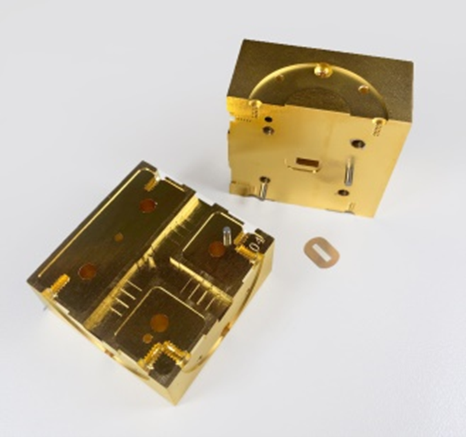
Fig. 3(a)
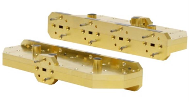
Fig. 3(b)
Fig. 3. Photographs of the manufactured (a) E-band magic tee, and (b) V-band four-way in-line power divider.
Both the E-band magic tee and V-band power divider were tested using a vector network analyzer (VNA). The ports of the magic tee are indexed as shown in Fig. 2. The measured return loss, isolation and insertion loss of the E-band magic-tee are presented in Fig. 4 for the full E-band frequency range. As shown in Fig. 4 (a), the H port and collinear ports show the minimum return loss of 20 dB, while the E port demonstrates the minimum return loss of 18 dB across the full waveguide band. As shown in Fig. 4 (b), the minimum isolation level between two collinear ports is around 21 dB. Meanwhile, the minimum isolation level between E and H ports is around 29 dB. The insertion loss of two collinear ports to E port is shown in Fig. 4 (c). The maximum insertion loss of the two in-phase output ports is estimated to be 3.7 dB. The measured return loss, isolation and insertion loss of the power divider are presented in Fig. 5. Port 5 indicates the input port and ports 1, 2, 3 and 4 indicate the four output ports. The input port has a typical return loss of 20 dB, and minimum return loss of 14 dB, while the output ports have a minimum return loss of 20 dB. The minimum isolation between output ports is around 18 dB, while the maximum insertion loss is around 7.2 dB across the full frequency band. The improved magic tee junction is implemented in other waveguide bands up to WR-06 to cover 170 GHz with satisfactory and consistent performance in a manufacturing environment.
[2] K. C. Hwang, “Design and optimization of a broadband waveguide magic-T using a stepped conducting cone,” IEEE Microw. Wireless Compon. Lett., vol. 19, pp. 539–541, Sep. 2009.
[3] A. A. Sarhan et al., “Simulation and implementation of a new X-Band 1:4 power divider/combiner based on a new waveguide H-plane folded magic-T,” Progr. Electromagn. Res., C, vol. 54, pp. 49-56, 2014.
[4] Y. Li et al., “A W-band miniature power divider based on E-faced-folded magic-T junction,” IEEE MTT-S International Microwave Workshop Series on Advanced Materials and Processes for RF and THz Applications (IMWS-AMP), July, 2016.
[5] M. Gholami, R. E. Amaya, and M. C.E. Yagoub, “Low-loss compact power combiner for solid state power amplifiers with high reliability,” IET Microw. Antennas Propag., vol. 10, issue. 3, pp. 310-317, Feb., 2016.
[6] L. Guo et al., “A waveguide magic-T with coplanar arms for high-power solid-state power combining,” IEEE Trans. Microw. Theory Techn., vol. 65, pp. 2942–2952, Aug. 2017.
[7] Y. He, D. Mo, Q. Wu, and Q. Chu, “A Ka-Band Waveguide Magic-T With Coplanar Arms Using Ridge-Waveguide Transition,” IEEE Microw. Wireless Compon. Lett., vol. 27, pp. 965–967, Nov. 2017.
[8] R. Beyer, and U. Rosenberg, “CAD of magic tee with interior stepped post for high performance designs,” in IEEE MTT-S Int. Microw. Symp. Dig., June, 2003.
[9] C. Guo et al., “A 3-D printed E-plane waveguide magic-T using air-filled coax-to-waveguide transitions,” IEEE Trans. Microw. Theory Techn., vol. 67, pp. 4984–4994, Dec. 2019.
[10] J. Wu, C. Wang, and Y. Guo, “Ridged waveguide magic tees based on 3-D printing technology,” IEEE Trans. Microw. Theory Techn., vol. 68, pp. 4267–4275, Oct. 2020.
[11] C. A. Leal-Sevillano et al., “Compact broadband couplers based on the waveguide magic-T junction,” Proceedings of the 43rd European Microwave Conference (EuMC), Oct., 2013.