Low Cost Ka-Band Transmitter for CubeSat Systems
Published: 2017, TWIoS IEEE
Abstract — CubeSat platforms grow increasingly popular in commercial ventures as alternative solutions for global Internet networks, deep space exploration, and aerospace research endeavors. Many technology companies and system engineers plan to implement small satellite systems as part of global Low Earth Orbit (LEO) inter-satellite constellations. High performing low cost hardware is of key importance in driving these efforts. This paper presents the heterodyne architecture and performance of a Ka-Band Integrated Transmitter Assembly (ITA) Module, which could be implemented in nano/microsatellite or other satellite systems as a low-cost solution for high data rate space communication systems. The module converts a 0.9 to 1.1 GHz IF input signal to deliver linear transmission of +29 dBm at 26.7 to 26.9 GHz frequency range with a built-in phase locked oscillator, integrated transmitter, polarizer, and lens corrected antenna.
Index Terms — CubeSat, Integrated Module, Ka-Band, Low Earth Orbit, Microsatellite, Nanosatellite, Transmitter

Fig. 1. SAGE Millimeter, Inc.’s Ka-Band Integrated Transmitter Assembly.
Current projections suggest significant and continued growth in the nano/microsatellite market for the next decade. Additional Ka-Band Transmitters are anticipated to be launched in various space missions for commercial research space programs within the next four years [3]. These developments reveal the increasing market for small satellite missions from commercial space ventures for applications in scientific research, planetary observation, and remote sensing [4]. Because these satellites have requirements for high speed data transmission rates, operating in the Ka-Band spectrum is a better design decision compared with previously accepted approaches. The Ka-Band spectrum allows system integrators to implement broader bandwidth millimeterwave systems that can link to ground stations hundreds of times faster than current methods, avoiding the congested and noisy S-band spectrum [4].
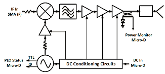
Fig. 2. Ka-Band Integrated Transmitter Assembly Block Diagram.
The Ka-Band ITA is a millimeterwave heterodyne upconverter specifically designed for CubeSat and small satellite platforms. Internally, the system utilizes a hybrid design consisting of monolithic microwave integrated circuits (MMIC), surface mount technology, and an optimized resonator waveguide filter for its millimeterwave operation with DC conditioning circuitry. With its size at 3.78” (W) x 3.44” (L) x 4.43” (H) and weight at 24 oz., it is both compact and light-weight. The block diagram of the ITA shown in Figure 2 includes a phased lock oscillator (PLO) at 12.9 GHz, a subharmonically pumped mixer (SHM), a waveguide bandpass filter (BPF), a right-hand circular polarizer (RHCP) and a lens corrected antenna (LCA). The phase locked oscillator provides a durable form factor that allows the ITA to withstand unforgiving shock, vibration, and temperature environments with optimum phase noise performance. The local oscillator (LO) section of the module incorporates a 100 MHz crystal oscillator internally referenced to a Varactor tuned dielectric resonator oscillator feeding into a subharmonically pumped mixer. A 1.0 GHz intermediate frequency (IF) signal is mixed with the 2nd harmonic of a 12.9 GHz signal generated by the LO signal source to up-convert to a 26.8 GHz RF signal. Implementing a subharmonically pumped mixer allows a less demanding phase locked oscillator to operate at millimeterwave bands. Operating at half of the RF frequency not only greatly reduces manufacturing demands and costs but also eliminates the undesirable harmonic and spurious content dramatically with high isolation.
The manufacturing of the ITA’s RF signal path is accomplished with conventional die attach and wire-bonding techniques to ensure high device performance. The microwave interconnects and matching networks of the transmitter’s building blocks are etched on a fiberglass reinforced laminate, providing excellent compatibility, repeatability and robustness in manufacturing process with wire-bondable MMIC devices. In addition, the use of hybrid microwave and millimeterwave technologies allows for integration and miniaturization of the module into a small compact form [5]. This is crucial in CubeSat platforms, in which size, power consumption, and efficiency are especially budgeted to strict margins. The RF transmission cascade following the mixer consists of an optimized millimeter waveguide bandpass filter with waveguide to microstrip transitions for robust harmonic and spurious suppression. A driver amplifier and a balanced high power amplifier allows for highly linear output power to satisfy the downlink system requirements. The DC conditioning circuitry incorporates linear drop-out and inverting regulators for pHEMT device sequencing biasing. This approach made powering the integrated circuits within the module via a single positive voltage possible. Overall, the transmitter achieves +29.5 dBm typical output power at the 1 dB compression point with approximately 23 dB IF to RF gain. At the output of the final balanced high power amplifier (HPA) stage, the up-converted RF output signal passes through a coupler in which a sampled portion of the RF power is sent to power detection circuitry for constant output power monitoring. A thermal sensor for case temperature indication and a PLO status indicator are included and are externally collected by a 15-pin micro-D connector. Out of the HPA, the transmitting signal is coupled into the rectangular WR-28 waveguide via an integrated microstrip to waveguide probe transition. A waveguide E-plane bend is used to couple the transmitting signal into a circular polarizer and lens antenna for efficient power radiation. The antenna assembly has 23 dBi gain, which allows the module to deliver over +50 dBm EIRP for the final transmitted signal. The entire module dissipates about 12 Watts DC power with a power added efficiency of 8%, typically.
The measured antenna Far-Field Pattern of the circular polarized lens antenna taken at the center frequency of 26.8 GHz configured for Right Hand Circular Polarization (RHCP) is shown in Figure 4. The 3 dB beamwidth at 26.8 GHz was 10.2 degrees with a gain of 23.3 dBi. The maximum side lobes level was -26.0 dB, which exceeded the specification of -20 dB.
Finally, the ITA was tested in a thermal-cycled temperature chamber. The frequency display of the ITA output signal is shown in Figure 5 and confirms the spectrum purity, output power, and harmonic and spurious level rejections of the final ITA module. The tests were performed at -25°C, +25°C and +65°C temperature, selectively. The space hardware standard qualifications were performed with the satellite.
[2] M. Q. Shafique, I. E. Rana, Journal of Space Technology, vol. 5, no. 1, pp. 124-133, July 2015.
[3] “Small Satellite Market Observations.” Internet. http://www.spaceworksforecasts.com/docs/SpaceWorks Small_Satellite_Market_Observations_2015.pdf, [Jul. 30, 2016].
[4] “Ka-Band Represents the Future of Space Communications.” Internet. www.nasa.gov/mission_pages/station/research/news/ka_band, [Jul. 30, 2016].
[5] “Sub-assemblies and Modules.” Internet. www.sagemillimeter.com/subassemblies-modules, [Jul. 30, 2016].